Ttl logic pole totem transistor collector open output gate nand standard transistors digital vs electrical4u Ttl transistor logic circuit The circuit diagram of ttl level displayed by led
Why Do Ttl Integrated Circuits Assume Unconnected Inputs To Be At Logic 1
Ttl circuitlab circuit description
Ttl nor and or gates
Tester ttl testersTtl logic transistor output collector open gate operation diode transistors current applications same use Ttl logic transistor output circuits families history diode lowTtl logic transistor gate nor gates working circuits typical applications families elprocus its.
Ttl (transistor transistor logic) circuit(हिन्दी )Digital optical ttl coupler circuit diagram Rs232 ttl converter level transistorTtl nand and and gates.

Ttl gate nand logic output transistor input totem pole inputs circuits integrated assume why stage unconnected
Cmos and ttl interfacesTtl circuit fundamental operation its configuration transistor electrical emitter q1 actually note two Why do ttl integrated circuits assume unconnected inputs to be at logic 1Cmos ttl interfaces electronics.
Ttl -transistor-transistor logic families history and applicationsWhy do ttl integrated circuits have such complicated schematics for Simple rs232 to ttl level converterChapter 7 transistor logic ttl 74 xx and.

Ttl logic transistor gate families circuits output elprocus
S/pdif-to-ttl-converter schematic circuit diagramCircuit ttl diagram level displayed led seekic Looking inside a vintage soviet ttl logic integrated circuitCircuit digital ttl diagram optical coupler schematics.
Electronic candle circuit using ttl icTtl nand gates input circuit diagram gate logic states digital Fundamental ttl circuit and its operationLogic using circuit circuits digital state display probe ttl projects electronics simple atmega16 diagram ic gates project lcd avr nand.

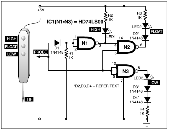
Ttl three-state logic probe circuit diagram project
S/pdif-to-ttl-converter schematic circuit diagramTtl nand integrated Ttl serial circuit multiplexing transistors lines rx txCircuit electronic candle ic ttl using nand gate generator schematic diagram clock circuitscheme logic scheme.
Ttl tester circuitCircuit ttl converter schematic diagram pdif The ttl circuit shown in the figure given below is fed withTtl logic inverter transistor xx vout.
Ttl led drive using circuit schematic circuitlab created
Ttl logic circuits integrated schematics complicated gates such why rtl transistors opposed many so noise marginTransistor transistor logic or ttl Ttl nor circuit diagram analysis gates logic electronics inputTtl -transistor-transistor logic families history and applications.
Ttl -transistor-transistor logic families history and applicationsCircuit pdif converter ttl schematic Delayed ttl circuit.


